
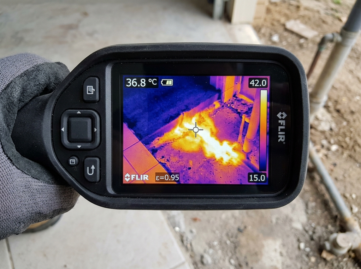
Water escaping from hot water supply lines transfers thermal energy through the sub-slab gravel bed and upward into the concrete floor. Utilizing high-sensitivity radiometric infrared cameras, diagnostic plumbers can visually map the exact heat bloom signature on tile, vinyl, and hardwood floors in real time.
| Specification / Diagnostic Metric | Engineering Standard / Detail |
|---|---|
| Camera Technology | Radiometric Long-Wave Infrared (LWIR) sensor |
| Thermal Sensitivity (NETD) | < 40 mK (0.04°C) difference detection |
| Infrared Resolution | 320 × 240 to 640 × 480 true focal plane array |
| Applicable Surfaces | Bare concrete, ceramic tile, laminate, engineered wood, vinyl plank |
| Optimal Target | Domestic hot water supply lines, radiant floor heating runs |
| Secondary Tools Required | Acoustic ground sensor or pinless moisture meter confirmation |
How Infrared Thermography Sees Beneath Concrete
Infrared cameras do not "see through" concrete like X-ray machines. Instead, they measure micro-variations in surface electromagnetic radiation in the infrared spectrum (7.5 to 14 µm) and convert that data into an accurate temperature thermogram.
When a pressurized hot water pipe fails below a foundation, escaping 120°F to 140°F water saturates the surrounding gravel base. Through thermal conduction, that heat energy migrates vertically through the solid concrete mass. Within 30 to 60 minutes, a distinctive, circular or elliptical thermal plume registers on the floor's finished surface, typically measuring 3°F to 15°F warmer than surrounding flooring areas.
Recognizing False Positives in Thermal Scanning
Experienced technicians differentiate slab leak plumes from solar heating through windows, HVAC supply ducts embedded in concrete, and refrigerator compressor motor heat by cross-verifying with pressure decay gauges and digital moisture meters.
What a Real Slab Leak Thermal Signature Looks Like
A genuine hot water slab leak displays three distinct thermal zones on a high-resolution radiometric display:
- Zone 1: Core Epicenter: The hottest point of the plume, exhibiting highest delta-T and sharpest temperature gradient. This marks where pressurized fluid directly contacts the underside of the slab.
- Zone 2: Dissipation Ring: An elliptical gradient where heat disperses outward through moisture absorption in the concrete matrix.
- Zone 3: Linear Pipe Thermal Trail: The faint linear signature of the warm copper tube leading up to and past the point of rupture.
Flooring Materials and Their Thermal Transmissivity
| Flooring Material | Thermal Conductivity | Thermographic Clarity | Diagnostic Notes |
|---|---|---|---|
| Ceramic & Porcelain Tile | High (1.0 – 1.8 W/m·K) | Excellent / Instant | Sharp heat bloom boundaries; easy pinpointing |
| Bare Polished Concrete | High (1.2 – 1.7 W/m·K) | Optimal | Zero thermal insulation; highest diagnostic accuracy |
| Luxury Vinyl Plank (LVP) | Moderate (0.2 – 0.4 W/m·K) | Good | Slight delay in thermal conduction; clear outline |
| Engineered / Solid Hardwood | Low (0.10 – 0.15 W/m·K) | Moderate | Wood insulates heat; requires longer scan times |
| Plush Carpet with Dense Pad | Very Low (0.05 W/m·K) | Difficult | Acts as thermal barrier; technicians pull back carpet edge |
Limitations: When Thermal Imaging Needs Acoustic Backing
Thermal cameras are an incredible non-destructive first-response tool, but certified diagnostic technicians understand their limitations:
- Cold Water Blind Spot: As noted in acoustic diagnostics, cold water line ruptures do not emit a distinguishable heat signature against ambient foundation temperatures.
- Soil Convection Drift: If a slab rests on loose aggregate or sloped bedrock, hot water may run downhill beneath the plastic vapor barrier for several feet before contacting the concrete slab, creating a displaced thermal bloom.
- Verification Requirement: A thermal anomaly must always be corroborated with an acoustic ground geophone before any floor is opened for repair.